The use of Formal Methods in human-computer interaction dates back to its earliest days as a growing discipline, including Phyllis Reisner's use of BNF to specify user interfaces in 1981 (Reisner 1981) and the author's own first paper on the topic at the first British HCI Conference in 1985 (Dix and Runciman 1985).
To some extent, Formal Methods sit uneasily within interaction design. Human beings are rich, complex, nuanced, engaged in subtle and skilful social and material interactions; reducing this to any sort of formal description seems at best simplistic. And yet that is precisely what we have to do once we create any sort of digital system: whether an iPhone or an elevator, Angry Birds or Facebook, software is embedded in our lives. However much we design devices and products to meet users’ needs or enrich their experiences of life, still the software inside is driven by the soulless, precise, and largely deterministic logic of code. If you work with computers, you necessarily work with formalism.
Formal Methods sit in this difficult nexus between logic and life, precision and passion, both highlighting the contradictions inherent in interaction design and offering tools and techniques to help understand and resolve them.
In fact, anyone engaged in interaction design is likely to have used some kind of formal representation, most commonly some sort of arrow and sketch diagram showing screens/pages in an application and the movements between them. While there are many more complex formal notations and methods, these simple networks of screens and links demonstrate the essence of a formal representation. Always, some things are reduced or ignored (the precise contents of screens), whilst others are captured more faithfully (the pattern of links between them). This enables us to focus on certain aspects and understand or analyse those aspects using the representation itself (for example notice that there are some very long interaction paths to quite critical screens).
What is Formal?
As with all words, “formal” is used to mean different things by different people and in different disciplines. In day-to-day life, formal may mean wearing a dinner jacket and bow tie or using proper language. That is, formal is about the outward form of things — a formal greeting may belie many emotions beneath the surface.
Taken strongly, formalism in mathematics and computing is about being able to represent things in such a way that the representation can be analyzed and manipulated without regard to the meaning. This is because the representation is chosen to encapsulate faithfully the significant features of the meaning.
from (Dix 2003)
29.1 Kinds of Formal Methods in HCI
There are very many kinds of formal or semi-formal notations, models and techniques used within HCI. One way to categorise them is by what gets represented:
users — Various forms of cognitive models have been used to analyse interaction, from cognitive architectures such as SOAR (Laird 2008) or ACT-R (Anderson 2005) to motor level models. The latter have continued to be surprisingly influential, however they are largely limited to numerical fitting of data with a few exceptions such as Eslambolchilar's work using control theory to model the cybernetic interaction between human movements and digital devices (Eslambolchilar and Murray-Smith 2010); (Eslambolchilar 2006). Task analysis and task models (Diaper and Stanton 2003) are also aimed at analysing or recording the behaviour of users, whether on existing systems or planned systems. Some task modelling systems take into account multiple users (e.g. CTT (Paterno 1999)), and there has been some modelling within the CSCW community (e.g. (Ellis 1994); (Dix et al. 2000) ); however, modelling at the group or social level is rare.
system — The other side of the interaction is the device or system that the user is interacting with. Many techniques have been applied to modelling the system behaviour including formal grammars, state machines, specification languages from theoretical computer science, and plain sums! While the focus of this kind of model or representation is the thing (computer, consumer device), this does not mean the user has been ignored. Rather, the needs of the user are expressed in the properties examined, or in the choice of what aspects to model.
world — Representations of the context of interaction can be very insightful: users are interacting with devices in a physical context, and their digital interactions may well have physical consequences, whether it is the controls of an aeroplane, or simply printing. However, models that take this into account are surprisingly rare. One example has been the use of space syntax, techniques developed within architectural theory in order to understand people’s movements and visitation patterns in urban or office spaces (see Section 4.1), and the author's own work has included modelling of interactive art installations (see Section 4.2). Context-aware interfaces (see Chapter 14) also often build some form of internal model. Later in this chapter, we will look at modelling of physical devices that include aspects of both system and world.
The representations of the user, while certainly formal, are typically not what is thought of as 'Formal Methods' and are likely to be dealt with in other chapters. Also, as noted above, representations of the world are rare, so the rest of this chapter focuses principally on Formal Methods applied to the system.
However, this itself has many variants:
at what architectural level do we represent the system? — This may be focused on presentation details, for example to assess the visual discrimination of items, or Fitts' Law timings of user actions; it may be at the dialogue level expressing the order of potential user actions and user responses, or at a deeper level analysing or modelling the underlying functionality insofar as it impacts on the user.
at what level of abstraction do we represent a system? — We may have a very concrete model of a particular system design, or we may opt for a more generic/abstract model in order to investigate some property irrespective of the particular system in which it is found. An example of the latter is analysis of undo functionality, discussed in Section 3.3.
for what purpose are we representing the system? — We may create a formal representation to be part of the execution of a running or prototype system. Alternatively, we may use the formal representation to perform automated or hand analysis (e.g. average number of keystrokes between different system states). Finally, it is often the case that it is the process of formalising that gives the analyst a deeper understanding of the system being studied.
29.2 Just sums - ad hoc calculations
Straightforward mathematical calculations are everywhere in HCI. These range in complexity. At the simplest level is simple arithmetic, for example, in the GOMS keystroke-level model (Card et al. 1980); (Card et al. 1983). The models behind information foraging theory are more complex, using differential equations (Pirolli 2007). In areas such as visualisation, information retrieval, and graphics, mathematics is again central.
Even small 'back of the envelope' calculations can be surprisingly effective in helping one to understand a problem. We will look at two such examples: screen typing and menu depth, then at the more complex mathematics behind "five users are enough".
29.2.1 On screen typing
Some years ago, comparisons of graphical vs. more textual interfaces (and they do still exist!) often used the idea that graphical displays have high 'bandwidth'. This obviously should be interpreted in terms of visual perception, not just raw pixels per second, but for output it seems fairly reasonable. But what about input, do screen buttons and icons increase the input bandwidth? In fact, a quick Fitts' law calculation shows that no matter what the number and size of the screen buttons, a reasonable typing speed is always faster (see box). The difference is that whereas the lexicon of the keyboard is fixed and has to be interpreted by the user in any context, GUIs can be contextual, showing appropriate actions (if you know any information theory, this is a form of adaptive compression). Notice that a small mathematical argument can lead to a design perspective.
Revisiting these calculations, many years later, they are perhaps more relevant in the face of on-screen keyboards in smart-phones and pad devices. To some extent, the early calculations are borne out in recent studies of iPad on-screen keyboards, which have found ratios more like 2:1 for keyboard to screen typing.
Back of the Envelope — keyboard vs. screen typing
Compare keyboard with screen for rate of entry measured in bits per second.
Keyboard:
Take typing times from KLM times quoted in (Dix et al. 2004).
nos targets – 64 keys
good typist – 9 keys per sec.
rate = 9 * log2(64) = 54 bps
Screen:
Screen width W with items size S on it. The average distance to target is half the width. To make calculations easier, assume a square screen and that the screen is completely filled with targets.
Fitts' Law – 0.1 log2 ( D/S + 0.5 )
D = W/2
nos items – (W/S)2
rate =
log2 ( (W/S)2 )0.1 log2 ( W/2S + 0.5 )
≈
2 log2 ( W/S )0.1 log2 ( W/S )
=
20 bps
So, screen clicking is nearly three times slower than typing!
29.2.2 Optimal menu depth
Often the 7+/–2 rule (Miller 1956), which is about working memory, is mistakenly over applied. One example is for menu systems, and you may well have seen suggestions that the number of menu items per screen (e.g. on a web page) shouldn't exceed 7+/–2. On a touch screen, large targets are easier to hit, again suggesting that small numbers of larger targets are a good idea. However, the fewer menu items on a single screen, the more menu levels are required to find particular content. Let's assume there are N items in total and you choose to have M menu items per screen. The depth of the menu hierarchy, d, is given by:
d =
log N / log M
If we look at a single display, the total time taken will be the time taken to physically display the screen and the time taken for the user to select the item, all times the number of levels:
Ttotal =
( T display+ Tselect ) x d
Using Fitts' law for Tselect and the formula for d, we get:
Ttotal =
( Tdisplay + A +B log M ) x log N / log M
=
( (Tdisplay + A)/ log M + B ) x log N
Notice that the effect of the increased number of screens exactly balances the gains of larger targets and that the only factor that varies with the number of menu items is the per screen costs (Tdisplay+ A). This suggests that the more items per screen the better. Look at virtually any portal site, and you'll see that practical experience has come to the same conclusion!
In fact there are extra factors to consider; for very small targets, Fitts' law starts to break down, which puts lower limits on target size. Also errors are very significant as this causes wasted screen displays, so smaller numbers of well-explained items may be better. For larger numbers of items, a further factor sets in, the time taken for the user to locate an item on the display. There is evidence that for linear menus, the actual select time is closer to linear than logarithmic. Redoing the calculations shows that this visual search becomes the limiting factor for larger screens, leading to a maximum menu size depending on refresh time (which is still much larger than 7+/-2 for most cases!) However, good design of screen organisation and sub-headings can push this visual search back towards the logarithmic case (see (Larson and Czerwinski 1998)). For WAP with small scrolling displays, the figures are again different.
Notice that being precise forces us to make assumptions explicit, and also, focusing on the critical factors helps us look for potential design solutions.
29.2.3 Five users are enough
Most people working in HCI and interaction design have heard "five users are enough", whether as a justification of a small study, or to refute one with fewer than five. In fact, this is grossly over-used and misapplied, probably more so than Miller's 7+/-2. Here we'll just look at the underlying mathematical model, but see (Dix 2011) for a detailed analysis of why "five" is not a sufficient answer to "how many users are enough?"
In fact, the roots of "five users are enough" originally lay in an analysis of empirical data by Nielsen and Landauer (Nielsen and Landauer 1993). They gathered data from user testing in a number of medium to large software projects. The data they gathered included the number of users studied in each cycle of development, the number of problems found by each user, and whether these were shared with other users. Also, and crucially, they measured the costs of performing each user study and the costs of creating a fresh iteration of the software.
They then used mathematics developed in software engineering to model program debugging, treating user interface problems discovered by user studies, or heuristic evaluations as analogous to coding bugs uncovered during software testing. Each bug (user interface defect) is regarded as equally likely to be found during any period of testing and totally independent of other bugs. The overlap between bugs found during different test runs can be used to estimate the likelihood of finding a single bug, and then this can be used, inter alia, to estimate the likely number of as yet undiscovered bugs. This is similar to mathematics used by biologists when doing capture/recapture studies to assess survival rates in populations of wild animals.
The analysis (given the assumptions) shows that the number of new problems found decreases exponentially with the number of additional users, and this can be used to create a cost-benefit graph where the maximum (averaged over different kinds of projects) turned out to be around 5 for heuristic evaluation ... although closer to 3 for user testing (largely because they were deemed more costly). After this, it was more cost-effective to perform an iterative development step (which is assumed, counter to previous assumptions, to 'reset the clock' for user interface problem discovery).
As noted, this result has been widely misapplied (Dix 2011), but we can draw two general lessons:
mathematical models can be incredibly influential
it is important to understand critical aspects of these models when applying the results, notably the underlying assumptions
the formality of the models makes it easier to explore the precise nature of these underlying assumptions, and therefore possible to assess the scope of applicability
29.3 Detailed system specification
29.3.1 Dialogue notations - what to do when
In day-to-day life, dialogue is a conversation between two or more parties, usually, but not necessarily, cooperative.
In user interfaces, dialogue refers to the structure of the interaction, the syntactic level of human–computer ‘conversation’. Dialogue forms the middle of three layers of the user interface as identified in the early days of user interface development, especially in the Seeheim model (Pfaff and Hagen 1995):
lexical (presentation in Seeheim) – the shape of icons, actual keys pressed
syntactic (dialogue) – the order of inputs and outputs
semantic (functionality) – the effect on internal application/data
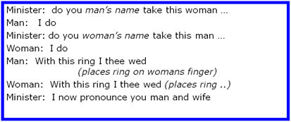
Of course, compared with human dialogue, human-computer dialogue is very constrained. However, some human-human dialogues are formal too. Think of a wedding service; it is a sort of script for three parties, which exhibits many of the properties of user interface dialogue:
It specifies order.
Some are contributions fixed – “I do”.
Others are variable – “do you man’s name …”.
The instructions for the ring are concurrent with saying the words “with this ring …”.
The author often asks people to go through the words when giving tutorials about dialogue. Imagine you have just done this, spoken the words to a complete stranger. Does it mean you are married to her/him? Of course not, the words are empty without meaning; they only carry legal weight if said in the right place, with a marriage licence, etc. They are purely the syntax of marriage, with none of the semantics.
Author/Copyright holder: Unknown (pending investigation). Copyright terms and licence: Unknown (pending investigation). See section "Exceptions" in the copyright terms below.
Imagine you are in a wedding service, but when asked, the woman says “I don’t”? Real dialogues often have alternatives. The wedding script doesn't cater for this; it assumes that people will work things out for themselves when unexpected things happen. However, when describing human–computer dialogues, we cannot assume the computer will be able to cope with the unexpected, so we have to consider all other alternatives, even if some of them might be 'do nothing'.
Sometimes, formal human dialogues do more clearly deal with these alternatives. In a trial, when the judge asks whether the defendant pleads guilty or not guilty, the process of the trial depends on the defendant's response.
Because people cope, the focus in formalised human dialogues is on normative responses, the standard trial process doesn’t cope with the Queen walking in and saying “off with her head”. Similarly, while specifications of human–computer dialogues need to be more complete, they will often ignore certain unlikely things, such as the user standing on the keyboard!
Let's see what you can do with dialogue notations and analysis.
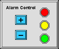
Imagine you are analysing the security control panel at a top secret establishment (Figure 1.A). It has two buttons labelled '+' and '–' that control the current alarm state. The alarm state can be at three levels, denoted by three lights: green, amber or red, and the buttons increase or reduce the level.
Author/Copyright holder: Unknown (pending investigation). Copyright terms and licence: Unknown (pending investigation). See section "Exceptions" in the copyright terms below.
Author/Copyright holder: Unknown (pending investigation). Copyright terms and licence: Unknown (pending investigation). See section "Exceptions" in the copyright terms below.
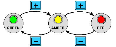
Figure 29.1 A-B: Top secret control panel: (A) control panel (B) state transition network
The image in Figure 1.A is the presentation level, what the panel looks like. A common way to specify the dialogue is using some form of state transition network (STN). Each major state or mode of the system is drawn as a circle, or sometimes as a thumbnail of the critical part of the visual display. The effects of the possible user actions (in this case the '+' and '–' buttons) are shown by the way they transform the states. Figure 1.B shows a state transition network for the control panel.
Just looking at the STN – without knowing what it is about – we can ask some questions: what does the '+' button do when the state is red, what does the '–' button do when the state is green? This is a formal analysis – we don't need to know what the STN means, but we can see just from the pattern that something is missing. In many applications, such as a program control for a television, we would probably want the '+' button to cycle back round from red to green, but in this application – an operator under stress perhaps – we would probably not want to risk accidentally changing from red alert to green. The formal analysis tells us that something extra is needed, the contextual understanding tells us what it is.
In this example, we have examined the diagram by hand, but an advantage of formal representations is that they can often also be analysed automatically. There are various forms of this.
Model checkers have been used in HCI research to verify whether certain desired usability properties are true (e.g. (Campos and Harrison 2001)). Note that these need to use quite sophisticated ways to cut down the total number of alternatives, as the number of possible paths through even a simple interface grows rapidly: if there were only 10 possible actions (icons, menu selections, valid keystrokes), then there are 100 possibilities for two actions, 1000 for three, ... Also the number of possible states grows rapidly. Imagine we have one option, say whether a font is bold, italic, bold-italic or neither: that has four states. Now, imagine a second option, say five possible font sizes at 9, 10, 11, 12 or 14 point: the number of possible font states is not 4+5, but 4x5=20. If we then add underline or not, we have 40 states. Because of this, model checkers use a combination of exhaustive and symbolic evaluation, but are still limited in the complexity of the systems they can analyse.
In fact, there are many safety-critical cases where the number of options is too large for human analysis, but can be dealt with by methods such as model checking, or other mathematical techniques such as graph analysis or matrix algebra. The FIT Lab at Swansea applies these techniques to medical instruments, allowing them to work out the likelihoods of different kinds of errors (Cairns et al. 2010).
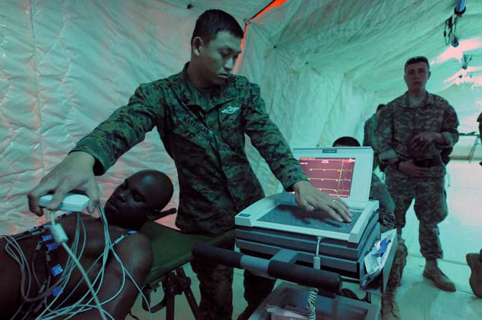
Author/Copyright holder: Courtesy of Bruce Cummins, US Navy. Copyright terms and licence: pd (Public Domain (information that is common property and contains no original authorship)).
Figure 29.2: Medical instruments is one example where the number of options may be too large for human analysis, but can be dealt with by methods such as model checking.
29.3.2 Executable system models
One of the uses of early dialogue notations was as part of prototype or deployed user interfaces. When coding user interfaces, whether point-and-click GUIs or web-based systems, it is easy to get lost in the effects of single actions, "when this button is pressed, what happens next". Various notations were common in the early days of user interface management systems (UIMS), including formal languages such as BNF, rule-based transition systems, and state transition networks (STNs). The last of these have been most common probably due to their graphical nature (even if usually translated into textual form for execution), and have continued to be used, for example, the Arrowlets framework for JavaScript-based user interfaces (Phang et al. 2008). However, other formalisms continue to be used, for example, Petri Nets have been used extensively, especially in work surrounding safety critical design such as air-traffic control (Navarre et al. 2001).
It is rare to see anyone outside a research lab use any of the most precise dialogue specification techniques, but link diagrams, such as those produced by Denim (Lin et al. 2000) and similar tools, are common, including some that are executable at least as prototypes, although these are not normally regarded as 'formal'. Also teams using UML are likely to use State Charts, although applied at a low level rather than for the dialogue.
Model-based user interfaces start modelling at a higher level than dialogue taking user task models and then refining these in stages to eventually obtain running systems. The CAMELEON reference model (Calvary et al. 2002) captures this at four levels:
Final User Interface (FUI) – The actual interface running on a particular platform and language with platform-specific widgets.
Concrete User Interface (CUI)– Here a Java Swing JButton and an HTML button () would be both described as a generic "Graphical 2D push button".
Abstract User Interface (AUI) – The interface is now abstracted in a modality independent way as 'abstract interaction objects' (AIO); so that a "control AIO" may be a 2D button on screen, or a physical button on the device. Also relationships between AIOs are defined in terms of spatial and temporal constraints, but not in terms of precise layout.
Domain/Task Concepts – At this level, the interface itself is all but forgotten. Instead, the focus is on what is wanted; for example "load a file" which then at a more concrete level may be rendered as a button launching a file selection dialogue.
This has been used in a number of systems including UsiXML (Limbourg et al. 2005); (www.usixml.org accessed March 2011), an XML-based collection of user-interface notations and tools.
29.3.3 Abstract system models
Both dialogue models and executable models are about a specific system being analysed or developed. However, Formal Methods can be applied to the analysis of broad issues that affect classes of systems.
Author/Copyright holder: Unknown (pending investigation). Copyright terms and licence: Unknown (pending investigation). See section "Exceptions" in the copyright terms below.
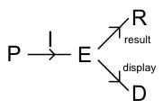
Figure 29.3: The PIE model
One of the earliest abstract models of this kind was the PIE model, developed by myself and colleagues at York in the mid-1980s (Dix and Runciman 1985). The PIE model treats an interactive system in input–output terms. The user input is some sequences of basic commands (e.g. individual mouse clicks, keystrokes). For historical reasons, the set of sequences of commands was denoted P (standing for 'program'). The traces of user commands are interpreted by the system (I denotes this function) giving rise to 'effects' (E) of various kinds from the internal system state to the bell sounding. Often there were two classes of effects: the more permanent results (R), such as the printed document and the moment-to-moment display (D). The latter whilst called 'display' also included effects such as haptic or aural feedback.
Variations were developed to allow analysis of issues of time, multi-window displays, and non-deterministic interactions (Dix 1987); (Dix 1990). Also, the basic PIE model was sometimes recast in terms of system states and an update function 'doit' as this was sometimes easier used to discuss and analyse problems. One of the nice things about using a formal model is that instead of arguing about which representation was the best, it was possible to write down the way they mapped on to one another:
doit( c, I(p) ) = I( p c )
and then we were able to use whichever was best for any job.
While very minimal, the PIE model allowed us to give precise definitions of a number of properties connected with the observability of the system, driven in no small part by the popularity of the idea of WYSIWYG ('what you see is what you get') at the time.
One of the simplest is:
∃ observe: D-> R st. ∀ e ∈ E : f( display(e) ) = result(e)
This says that there exists (∃) a function (called here 'observe') from displays to results, such that for all (∀) states of the interactive system (effects), the function applied to the current display gives you the current result. Or in other words, you can tell what you are going to get by looking at the current screen.
Of course, there are often parts of a document that are off screen, so more complex variants of these were specified to be able to say, "there is always some set of navigation commands that let you see enough to be able to tell the result".
These kinds of properties were then used by those with notations and tools for particular systems as things to check, either by hand, or using model checkers or other automated analysis tools.
Undo systems have been extensively studied, partly because they were a particularly hot topic at the time this work was first being done, partly because they have nice algebraic properties that are easy(ish) to handle using formalisms, and partly because they have a nasty edge case which make them hard to deal with or error prone to deal with informally.
One of the earliest results (Dix 1991) was to show that it is impossible to have a 'universal undo', that is a single 'undo' button, which would undo the previous action no matter what it was, including undo itself. At the time, there were various systems that had variants of toggle undo (swopping between two states), and some of these (it was claimed) obeyed the universal undo property.
The universal undo property can be framed (using the 'doit' representation):
∀ s ∈ E, c ∈ Cu doit( undo, doit( c, s ) ) = s
Let's go through the impossibility proof:
1) consider any state, s, of the system and any two commands a and b. Imagine the effect of either doing a or doing b. These will yield two states (typically different) sa and sb.
sa = doit( a, s ), sb = doit( b, s )
2) consider applying undo in states sa and sb, first state sa
doit( undo, sa ) = doit( undo, doit( a, s ) ) { expand }
= s { universal undo }
by the same argument doit( undo, sb ) = s also
that is undo in each case gets us back to the original state, just as we would expect
3) finally consider applying undo in state s. As well as being the original state, it was also the result of applying undo in state sa (step 2). That is, we might have done the sequence a, undo, undo. Mathematically:
doit( undo, s ) = doit( undo, doit( a, sa ) ) { from (2) }
= sa { universal undo }
however, equally the same argument applies if we think of b:
doit( undo, s )= doit( undo, doit( a, sb ) ) { from (2) }
= sb { universal undo }
So, the two states must be the same: sa = sb
As the argument started in step (1) by choosing any state and any pair of commands, this means wherever we are in the system, the effect of any command is always to do the same thing! It is as if there were only one button in the system, every keystroke, mouse click, or thumb on the back with a hammer does exactly the same thing. Furthermore, because undo of undo gets us back to where we started, it turns out there are at most two states in the system ... the light switch is the most complicated system that can have the universal undo property.
Author/Copyright holder: Unknown (pending investigation). Copyright terms and licence: Unknown (pending investigation). See section "Exceptions" in the copyright terms below.
Figure 29.4: Space syntax colouring
In fact, real undo systems never obey this property (they are more complicated than light switches!), but instead they are variants of two kinds of undo:
toggle undo where undo toggles you back and forth between the previous and current state, but you can never go back more than one step
stack undo where the system remembers a stack of previous states. Normal commands add to the stack (a partial history), and undo/redo navigates up and down the stack (like back and forward in a web browser). However, as soon as you do any normal command in the middle of doing undo/redo, the stack is chopped off where you are and the new state added instead.
Formal analysis of these alternatives led to analysis of the 'danger' points for stack undo (when a slip during deep undo/redo cycle can lose massive amounts of work), and it also provided a proof that toggle and stack undo were the only mechanisms that satisfied basic properties for undo (Dix et al. 19997). This analysis used a quite complex branch of mathematics called Category Theory, which is especially powerful for 'arrow chasing' proofs around diagrams like those in Figures 3 and 4.
Furthermore, the structural similarities between undo and browser back meant that the same analysis techniques were able to be applied to this also, distinguishing the fact that 'back' whilst apparently simple (like undo) was in fact subtly, but importantly, different in different kinds of systems.
There were many extant single-user undo systems at this point, but multi-user editing was still new. Formal analysis of multi-user undo allowed the potential problems and solution strategies to be identified before the first such systems were created. When group undo systems were created, they encountered exactly the problems and solutions that the formal analysis had uncovered.
This exemplifies one of the core strengths of Formal Methods, the ability to be able to analyse problems before actual systems exist.
29.4 Models of the world
As noted in Section 1, models of the world are more rare than models of computer systems, but can be very valuable. There are no clear categories of these, often being ad hoc to meet particular needs, so this section just gives three examples of quite different kinds of formal models.
29.4.1 Space syntax - modelling movement and significance in the world
Space syntax was initially developed by Hillier at the Bartlett School of Architecture in London (Hillier 1999). There were various works that attempted to describe issues of coherence or legibility of urban spaces, perhaps most influential Lynch's 'image of the city' (Lynch 1960), but Hillier was looking for a more rigorous, theoretical account and for more rigorous tools.
When looking at urban road networks, the obvious measure of 'distance' is not the crow-flies string stretched between points; unless you are in a tank or a helicopter, you cannot simply go through or over buildings. Instead, one is likely to measure the length of the path along roads (often called the 'Manhattan block' distance), maybe taking into account one-way systems for cars. If one were being a little more sophisticated, one might look at time taken. For pedestrians, this would be close to the walking distance, but for cars this might distort the map as city centres tend to be busy.
One of the key insights of space syntax is that none of these metrics captures the human sense of the city, and that central to this is line of sight. If two landmarks are within line of site to one another, they are in a sense linked and become 'close' in our mental model of the city. Furthermore, it is the major turnings that form psychological markers along the way. Space syntax uses these turnings as metric of distance. If you have to make 5 turnings to get from point A to B, then their space syntax distance is 5.
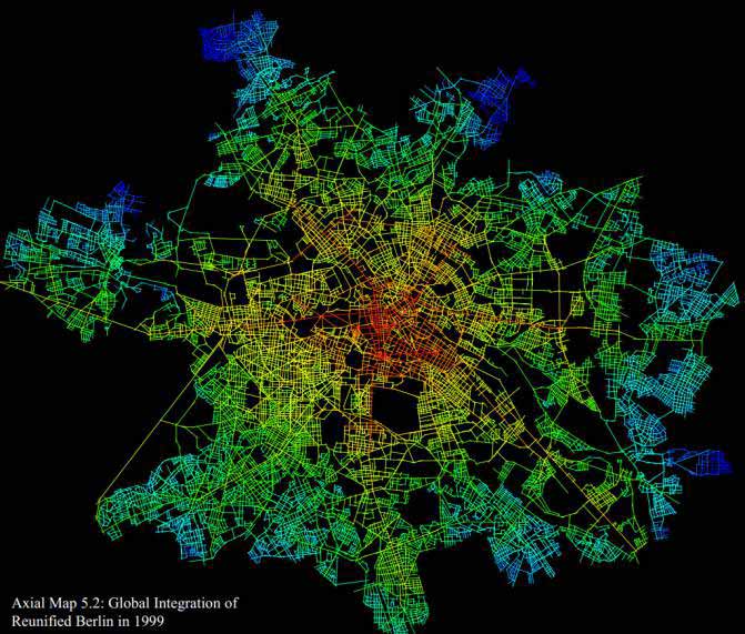
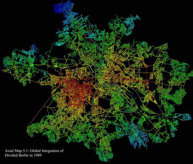
With this as a metric, locations in a city can be analysed to obtain a centrality measure: a place is more 'central' if its maximum/average distance to all other places is lower. With a crow-flies or Manhattan-block distance, this is likely to be close to the geometric centre of the city, but with the space-syntax turnings metric, it may end up in different places. Figure 5 A-B show the Berlin streets - before and after the unification - coloured according to the space syntax approach. The white line on Figure 5 B is the Berlin wall. Notice how the wall means that the most central area from a space syntax point of view (coloured red) is not in the centre of the city before the unification.
Author/Copyright holder: Jake Desyllas. Copyright terms and licence: All Rights Reserved. Reproduced with permission. See section "Exceptions" in the copyright terms below.
Author/Copyright holder: Jake Desyllas. Copyright terms and licence: All Rights Reserved. Reproduced with permission. See section "Exceptions" in the copyright terms below.
Figure 29.5 A-B: Space syntax colouring of Berlin - before and after the Berlin wall
This far, this is simply drawing pretty pictures, but the remarkable thing is that these measures of centrality can be compared with other measures, for example, the density of shops, restaurants, and other public meeting places. When this is done, the two are found to correlate very closely, that is the space-syntax measure drawn solely from the geometry of the city is a very strong predictor of the real, human heart of the city.
When the Berlin city analysis is repeated with the wall removed, the 'central' areas change accordingly in the space syntax analysis. Within a few years of unification, the busy areas of Berlin shifted; some areas that were previously quiet, residential areas became business or shopping areas. These shifts were perfectly in line with the space syntax predictions.
Similar analysis techniques are used for buildings, and they enable the planner to determine suitable places for meeting rooms, coffee areas, etc.
Space syntax has been used in HCI in two ways.
First, it has been used in order to understand digital interventions in physical spaces. For example, in the Cityware project, it was used to understand mobile application use including computational simulations of movements (Kostakos et al. 2010).
The second use has been in the generation of virtual environments. In the Tower project (Prinz et al. 2004), inhabited virtual spaces were built where users moved amongst representations of documents and folders, rather like those found in cyberpunk novels. Whereas a real city evolves, these are created spaces, and so space-syntax was used generatively to build 'intelligible' information spaces.
29.4.2 Belief and time - modelling an artistic performance
Art seems even more distant from Formal Methods than usability, and yet formalism has been used to make sense of artistic performance and art installations.
In certain kinds of performance art, the nature of who is the performer and who is the audience can be deliberately problematic. Imagine, in the midst of a crowded city square a group of performers, all wearing white hats, start to move in unison; this may not be obvious to those around them, but may be visible to someone on a high building. Similarly, if you are in a shopping mall and someone starts to behave oddly, it may take a while before you realise she is a mime artist. In the case of certain TV shows, the reaction of unwitting bystanders becomes part of the spectacle.
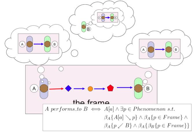
One key aspect of dramatic theory is the idea of the 'frame' bounded by time and (maybe virtual) space: whether it is the stage during a theatre performance, or the space around the juggler in the city square. To constitute a performance, the audience needs to be aware that there is a performance frame, and the performers need to know that their audience knows that there is a frame. This is all about belief, and so a form of belief logic has been used to model this.
Author/Copyright holder: Unknown (pending investigation). Copyright terms and licence: Unknown (pending investigation). See section "Exceptions" in the copyright terms below.
Figure 29.6: This figure shows the situation graphically and in logic. Alison performs to Brian if (i) Alison believes her actions are (potentially indirectly) observable by Brian, (ii) Brian believes the actions are part of a dramatic frame, (iii) Alison believes that Brian believes that the actions are part of the frame. This complex belief chain (A believes that B believes that A is doing something) is hard to think about, and so formalising helps to keep track of who knows what when. This was then used to analyse a particular installation Deus Oculi, which deliberately makes some of the interconnections between parts obscure. The analysis showed that the key 'aha' moment of the installation is precisely when a particular transition of beliefs occurs.
Author/Copyright holder: Unknown (pending investigation). Copyright terms and licence: Unknown (pending investigation). See section "Exceptions" in the copyright terms below.
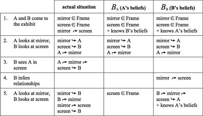
Figure 29.7: Deus Oculi - tableaux of beliefs as two people interact with the exhibit
29.4.3 Physigrams - modelling physical aspects of digital devices
The humble light-switch is nearly as ubiquitous as the word processor in the HCI literature. It has been analysed in terms of the cultural understanding implicit in its use, the mapping of switch direction to function (is down off or on?), the mapping between banks of switches and lights in a room, even accidentally switching off the lights mistaking it for the lift-call button (and the author once set off a fire alarm making the opposite mistake!). Here we are going to focus on the physical interactions of the light switch 'unplugged'.
We can think of the light switch as a two state device: lights on/off, you press the switch down and the light goes on, you lift it up and the lights go out. However, notice the "and the" in the previous sentence: there is first a physical interaction with the switch and then this gives rise to an effect on the light.
Author/Copyright holder: Unknown (pending investigation). Copyright terms and licence: Unknown (pending investigation). See section "Exceptions" in the copyright terms below.
Author/Copyright holder: Unknown (pending investigation). Copyright terms and licence: Unknown (pending investigation). See section "Exceptions" in the copyright terms below.
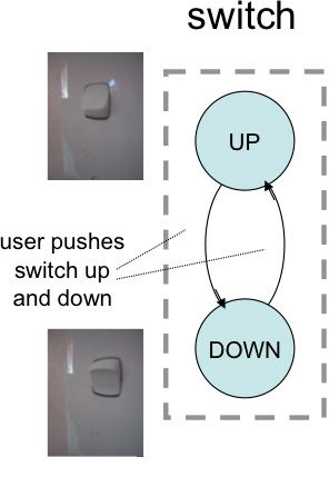
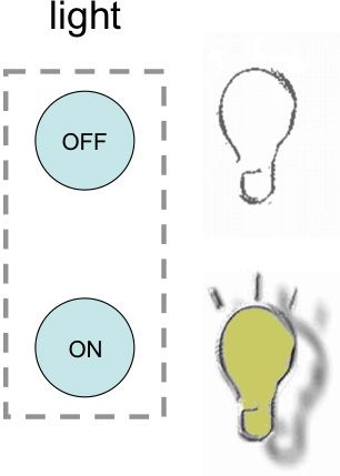
Figure 29.8 A-B: Light switch (A) physical device (B) logical states
Figure 8 separates out these two. On the left (Figure 8.A) are the two states of the switch itself, on the right (Figure 8.B) the two states of the light. Drawing both allows us to discuss issues such as the mapping between switch position and light state. In this case, it is fairly obvious, but in more complex devices, this mapping may be something we wish to analyse at length. Crucial to any such discussion is having both diagrams.
The one on the right, the light on/off state, would often be the complex digital state of a device, for example the current channel selections on a television. This is the kind of thing that Formal Methods deal with frequently in software engineering, and typical of the level of detail used in Formal Methods in HCI.
Author/Copyright holder: Unknown (pending investigation). Copyright terms and licence: Unknown (pending investigation). See section "Exceptions" in the copyright terms below.
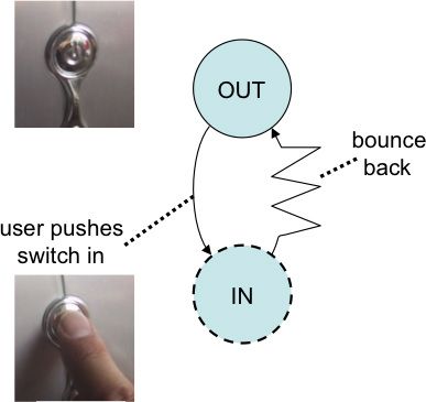
Figure 29.9: Computer light switch that 'bounces back' after you have pressed it
In contrast, the one on the left is about the physical light switch itself. It captures the interaction properties/affordances inherent in its physical potential, even if it were torn from the wall and disconnected from electricity – literally 'unplugged'. Imagine a small child playing with an old switch, simply pushing it back and forth.
Physigrams are a modified form of state transition network (STN) designed to specify these physical interactions. They are like a normal STN, but have some additional aspects in order to deal with the fact that physical behaviours are different from digital ones. For example, Figure 9 shows the physigram of the kind of press button switch you often find on a computer. Unlike the simple light switch, it is almost always in the same position; it appears very much like a one-state device! However, in fact it does have an 'in' state, but it only stays there while you are pressing, a tension state. The dashed line around the 'in' state indicates that it is a tension state, and the lightning-bolt arrow denotes the fact that the transition occurs autonomously because of the internal spring within the switch.
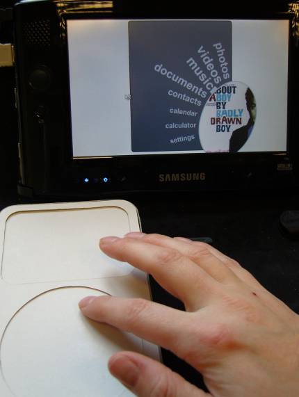
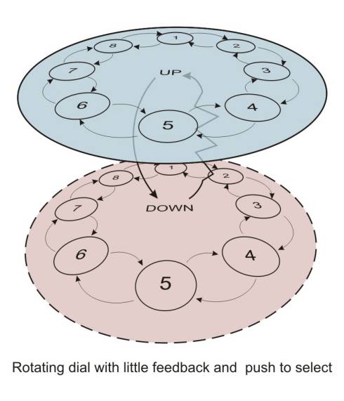
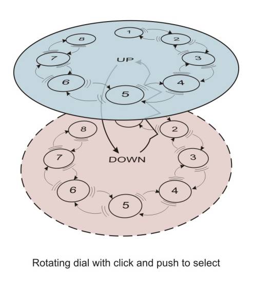
Often Formal Methods are regarded as being too difficult for use by 'ordinary' designers, and only suitable for experts. However, this kind of diagrammatic representation is quite accessible (indeed you find STNs in consumer guides). Figure 10 A-B and 11 A-B shows physigrams produced by product designers using them to compare the properties of two physical device designs for the same underlying digital functionality. While the devices were similar in many ways (circular control, managing a scrolling menu), the physigrams highlighted key differences, particularly the lack of tactile feedback in one of the devices (scroll pad).
Author/Copyright holder: Unknown (pending investigation). Copyright terms and licence: Unknown (pending investigation). See section "Exceptions" in the copyright terms below.
Author/Copyright holder: Unknown (pending investigation). Copyright terms and licence: Unknown (pending investigation). See section "Exceptions" in the copyright terms below.
Figure 29.10 A-B: Physigrams created by product designers

Author/Copyright holder: Unknown (pending investigation). Copyright terms and licence: Unknown (pending investigation). See section "Exceptions" in the copyright terms below.
Author/Copyright holder: Unknown (pending investigation). Copyright terms and licence: Unknown (pending investigation). See section "Exceptions" in the copyright terms below.
Figure 29.11 A-B: Physigrams created by product designers
29.5 A success story
It is often hard to measure the effectiveness of methods, especially if the claim is that they improve intangibles such as quality or maintainability. Furthermore, given the variability in people and projects, even large differences in measurable indicators, 30-50%, may be hard to detect. So, as an example, I am going to go back nearly 30 years, not because there haven't been any successes since then (!), but because the impact in this case was so dramatic, a 1000% (yes the ten-fold) increase in productivity.
29.5.1 The problem
This comes from personal experience, before I was an academic or had even heard of HCI. I was working for Cumbria County Council working on transaction processing programs in COBOL, the sort of thing used for stock control or point-of-sale terminals in large organisations.
While this all sounds like very old technology (mainframes!), in fact transaction processing systems are very like web-based systems: a message comes in from a terminal somewhere, it needs to be processed, a response is sent back, and the next message dealt with, usually from a completely different terminal.
The problems were not unlike those you sometimes see in web-based interfaces today: applications sometimes 'losing track' of where they are in interaction sequences, and exhibiting odd bugs, including once when a person on one terminal pressed 'next' on a listing screen and got an unexpected result, which turned out to be the 'next' page for a completely different terminal. Further more it took people a long time to produce this buggy code.
However, when you looked at the code, the lack of quality and efficiency was not surprising. Figure 12 gives a taste of what the code looked like.
if confirm_field is empty // can't be confirm screen<br /> // or user didn't fill in the Y/N box<br /> then if record_id is empty // must be initial entry <br /> then prepare 'which record to delete' screen<br /> else if valid record_id<br /> then read record and prepare confirm screen<br /> else prepare error screen<br /> else if confirm_field = "Y' <br /> then if record_id is empty // help malformed<br /> then prepare error screen<br /> else if valid record_id<br /> else do deletion<br /> then prepare error screen<br /> else if confirm_field = "N' <br /> then prepare 'return to main menu' screen<br /> else prepare 'must answer Y/N' screen
Figure 29.12: Typical 1980s transaction processing code
The URL structure of the web makes this a little cleaner, and I know some wonderful web programmers creating beautifully clean code. However, if you have looked at a lot of web interface code, not least those from big open source projects, this nest of choices and sub-choices is not uncommon. The focus is on a single page, a single transaction, and the developer is in a "what just happened, what happens next?" mode of thinking.
29.5.2 The solution
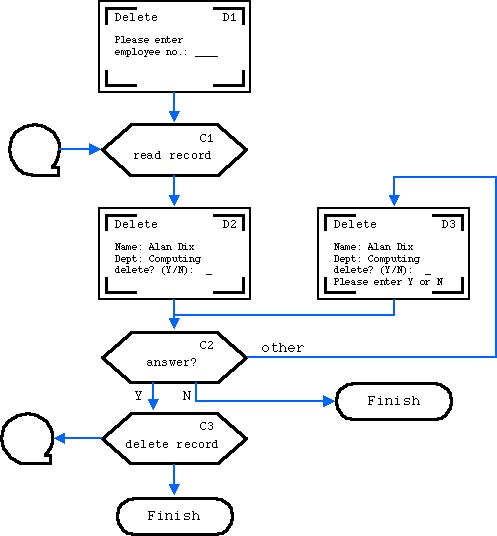
Faced with this, I knew I would not be able to make sense of it and so looked for a way to make it manageable. The most obvious tool to hand was the humble flow chart. However, rather than create a flow chart of the program code (the normal use), I used flow charts such as the one in Figure 11 that mapped out the main screens and actions between them. That is, I created a dialogue specification. The boxes describing the computer actions between screens were typically described quite loosely, saving a record to disk might require a whole raft of shuffling variables, calling file system code, etc., but this is what programmers do. The flow chart was about what was difficult: keeping track of the big picture.
Sadly, there were no automated tools, but by hand the paper flow chart was translated into templated code. Each screen corresponded to a block of code that assembled the message to send to the terminal, and each block of computation code to run after the screen. The small identifiers were used as labels (goto!) in the code, so that when there was any problem, or any change needed to be made, it was possible to easily find the corresponding code. They were also put at the top corner of the screen as an identifier so that users could give them as a code if there were any problems to report. Finally, the flow diagram meant it was easy to see whether one had tested all parts through the dialogue (not the same as all oaths through the code).
The most important thing, though, was speed. It was much faster to draw the flow chart and translate it into code than it was to simply write the code (and this is without any support tools). Even more dramatic was the differences in turnaround time after discussions with users. It is important to recall that these were the days before rapid application development; typically it would take many days or weeks to create and update this type of applications, but instead changes could be implemented in hours, around 10 times faster than standard methods.
Author/Copyright holder: Unknown (pending investigation). Copyright terms and licence: Unknown (pending investigation). See section "Exceptions" in the copyright terms below.
Figure 29.13: Flow chart of user interaction
29.5.3 Why it worked?
While this was a very successful application of Formal Methods in interface design, I didn't understand why at the time. It is only by reflecting in the intervening years that I came to understand the rich interplay of factors that made it work and guidelines to help reproduce that success.
useful – addresses a real problem!
The notation focused on the overall user-interface dialogue structure that was causing difficulties in the existing systems. So, often formalisms are proposed because they have some nice intrinsic properties, or are good for something else, but do not solve a real need.
appropriate – no more detailed than needed
For example, there was no problem in producing the detailed code to access databases etc., so the formalism deals with this at a very crude level 'read record', 'delete record' etc. Many formalisms force you to fill in unnecessary detail, which makes it hard to see the things you really need it for as well as increasing the cost of using it.
communication – mini-pictures and clear flow easy to talk through with client
Formal Methods are often claimed to be a means to improve communication within a design team because of their precision. However, when precision is achieved at the cost of comprehensibility, there is no real communication.
complementary – different paradigm than implementation
It is common to use specification methods that reflect the final structure of the system – for example, object-oriented specification for object-oriented systems. Here, however, this specification represents the structure of the dialogue, which is completely different from the structure of the code. This is deliberate: the notation allows one to see the system from a different perspective, in this case one more suitable for producing and assessing the interface design. The relationship between the structure of the notation and the structure of the code is managed via simple rules, which is what formalisms are good at!
fast pay back – quicker to produce application (at least 1000%)
The argument is often that Formal Methods will yield long-term time-savings. However, most people like instant pay-back. Spending lots of time up-front for savings later is very laudable, but developers and clients are often happier to see a buggy prototype than to be told that, “…yes, in a few months it will all come together.” The dialogue flowcharts didn't just produce long-term savings, but also reduced the lead-time to see the first running system.
responsive – rapid turnaround of changes
The feeling of control and comprehension made it easier to safely make changes. In some Formal Methods, the transformation process between specification and code is so complex that change is very costly (see (Dix and Harrison 1989) for a discussion of this). Of course, with user interfaces, however well specified, it is only when they are used that we really come to fully understand the requirements.
reliability –clear boilerplate code less error-prone
Although the transformation process from diagram to code was not automated, it was a fairly automatic hand process applying and modifying boilerplate code templates. This heavy reuse of standard code fragments greatly increases the reliability of code.
quality –easy to establish test cycle
The clear labelling of diagrams and code made it easy to be able to track whether all paths had been tested. However, note that these are not just paths through the program (which effectively restarted at each transaction), but each path through the human–computer dialogue.
maintenance –easy to relate bug/enhancement reports to specification and code
The screens presented to the user included the labels, making it easy to track bug reports or requests for changes both in the code and specification.
In short, the formalism was used to fulfil a purpose, and was, above all, neither precious nor purist!!
29.6 Barriers to acceptance
As noted in the introduction, Formal Methods have always sat a little uneasily within HCI, have never been popular with the CHI community, and can engender vitriol that is hard to explain in a discipline that is otherwise accepting.
A few years ago, as a meta-reviewer at an HCI conference I was forced to disregard one review completely as the reviewer's sole critique was to dismiss the paper simply because it was formal and this was clearly not an acceptable area; the author, it was suggested, should turn to ethnography or social science. Note, this was despite the fact that one of the workshops at the conference was on Formal Methods. It would be unthinkable to imagine a similar review dismissing an ethnographic or experimental paper simply because of the area.
To be fair, this probably reflects general trends in society (or at least Anglo-American society) where it is common to hear educated people boast about their innumeracy, whereas they would be deeply embarrassed by illiteracy. Furthermore, even within many computer science departments, the teaching of more formal topics has been reduced, as students' mathematical skills on entry do not make this, or topics such as graphics, achievable.
So, championing Formal Methods in HCI is not going to make you popular!
As well as requiring expertise, Formal Methods tend to be costly in terms of time taken, and it can be hard to justify large amounts of analysis time before any 'real' work appears to be done. There are long-term gains, it can be argued, but this is difficult to justify when the project is 3 months down the line and there is no code written yet. This has always been a problem, and more so with agile development techniques.
These cost barriers work at an individual area also. In my personal experience, when I have used Formal Methods extensively in real development, it has been obvious afterwards that the resulting systems were better designed, more robust and took less time to develop than more ad hoc approaches. However, despite knowing this, when faced with a new project, I just get in and hack! Extensive planning and preparation is worthwhile, but the bang for the buck comes late – it does not sit well with human psychology.
29.7 Future directions
Despite the barriers above and general disopprobrium, there are a number of groups who continue to produce strong work in the area, often working closely with the industry, and the model-based user interface development is an active stream in W3C. Furthermore, the various venues for this work: the DSVIS, EHCI and TAMODIA conference series, have become part of the new jointly IFIP and ACM sponsored conference EICS (Engineering Interactive Computer Systems). This covers a range of areas, but Formal Methods is a strong strand.
Given the costs of applying Formal Methods, it is not supporting that the areas where they have been applied most consistently over the years have been in safety critical situations, where the impact of mistakes is high and so the costs of employing Formal Methods acceptable. This is the case with, for example, the group at Toulouse, who use variants of Petri Nets in their work with air traffic control, and the group at Swansea using graph methods with medical instruments.
Looking more generally, however, it seems the time is ripe for growth.
On the web interfaces have to coordinate multiple API services, have to target different devices, and have multiple 'threads' of execution (session, window, strict chronology). In our homes and workplaces, multiple devices are beginning to 'talk' to one another, so that our interactions with a phone might have an effect on our TV or washing-machine, our central heating is responding to manual controls, external temperature, and smart grid dynamic pricing. Traditional functional design broke things, including user interface elements, into intellectually manageable chunks. In contrast, the complex interactions between simple elements are hard to make sense of and can lead to emergent effects that do not show up during normal testing. In Agile development, automated testing is central to the discipline, and yet often the user interface is least well represented in the test suite.
These are issues crying out for Formal Methods!
Given this, the adoption of model-based techniques by W3C groups focused on adaptation to different devices is not surprising. Also in the UK, there are several large projects looking at the complex interactions of human agents and software systems on the web, and strands of Web Science clearly overlap with this.
At a practical level, it is interesting to observe practitioners creating ad hoc declarative representations at different levels within web-based systems; often using JSON, turtle, XML or other generic data-representations to create special purpose notations. Just as in the 'success story', they are using these formal representations (although they would not call them this) because they work, because they make their life easier. They are not a chore, not medicine that will eventually make you better, but of value now.
A weakness in the Formal Methods community has been to recognise that designers and developers, as well as users, are actually human. To be fair, this is also a charge that could be levelled at user-centred design in general, as all HCI methods tend to be up-front heavy with the promise of future rewards, hence the important job that Randolph Bias and Deborah Mayhew did in "Cost Justifying Usability" (Bias and Mayhew 1994).
I would love to see this addressed by the next generation of researchers (or the current generations!). To some extent, this is happening in the model-based development area, but the notations still feel top-heavy. Ideally, we would be creating notations and tools that require just enough effort at each stage of use to create value at that stage. However, the cumulative overall effect of adding this 'just enough' formality will mean that there is a sufficiently complete formal representation to use for further analysis.
What are the notations that would mean that those practitioners did not need to create their own ad hoc notations each time?
29.8 Where to learn more
29.8.1 Books (in print or available online)
A. J. Dix (1991). Formal Methods for Interactive Systems. Academic Press. ISBN 0-12-218315-0 http://www.hiraeth.com/books/formal/
My own early monograph in the area. It includes PIE model and other models and methods. Although it is now 20 years old, I have recently found myself revisiting several of the techniques to apply to recent development projects.
The book is out of print, but the full text is available (free!) as PDF on the book web site (above).Paternó, F. (2000). Model-Based Design and Evaluation of Interactive Applications. London, Springer-Verlag.
Reviews a variety of models used in HCI, and then considers the whole design lifecycle using ConcurTaskTrees as a central representation. Note that the term 'model-based' here means models in general, not 'model-based user interface development' as discussed in Section 3.2, (although Fabio Paternó is also heavily involved in this area).H. Thimbleby, Press On — Principles of Interaction Programming, MIT Press, 2007, ISBN: 0262201704
Paperback edition, ISBN 978–0–262–51423–1, 2010.
This book is about programming interactive systems, but in it Harold explores in detail the use of various formalisms during construction and analysis,
29.8.2 Chapters
The following two chapters are available online, although sadly the excellent collections they were in are now out of print. Several sections of this encyclopaedia entry draw heavily on "Upside down As"
A. J. Dix (1995). Formal Methods. In Perspectives on HCI: Diverse Approaches, Eds. A. Monk and N. Gilbert. London, Academic Press. pp. 9-43. http://www.alandix.com/academic/papers/formal-chapter-95/
Upside down As and algorithms - computational formalisms and theory In HCI Models, Theories, and Frameworks: Toward an Multidisciplinary Science. John Carroll (ed.) ISBN 1-55860-808-7. Morgan Kaufman, 2003. pp. 381-429 http://www.alandix.com/academic/papers/theory-formal-2003/
Two chapters from my HCI textbook deal extensively with issues connected with formalism:
Chapter 16: Dialogue notations and design
Chapter 17: Models of the system
A. Dix, J. Finlay, G. Abowd and R. Beale (2004). Human-Computer Interaction, third edition. Prentice Hall. ISBN 0-13-239864-8.
29.8.3 Conferences
EICS: ACM SIGCHI Symposium on Engineering Interactive Computer Systems (annual since 2009).
eics-conference.org
This has a broader remit than purely Formal Methods, but the main players in the area tend to report there. Note that a number of older conferences amalgamated to form EICS (see below).FMIS: Formal Methods for Interactive Systems (annual/biannual since 2006)
fmis.iist.unu.edu/fmis_events.html
Smaller workshop dedicated solely to the topic.
29.8.4 Conferences (older)
The following conferences have amalgamated into EICS, but many key papers can be found in the old proceedings.
DSVIS: Design, specification, and verification of interactive systems. (annual 1994–2008). Probably the key annual venue for Formal Methods in HCI (although not limited to this).
EHCI: Engineering Human–Computer Interaction (triennial). Periodic conference organised by IFIP WG2.7/13.4 (User Interface Engineering), which is the only IFIP working group cross listed under two technical committees.
TAMODIA: Task Models and Diagrams (annual, 2002-2010)
CADUI: Computer Aided Design of User Interfaces (annual 2002??–2008)
29.8.5 Books (not in print, but maybe in library)
These are out of print, but a few copies are available second-hand online.
Harrison, M.D. and Thimbleby, H.W., editors (1990). Formal Methods in Human Computer Interaction. Cambridge: Cambridge University Press.
Harrison and Thimbleby's 1990 collection includes contributions from many of those working in the early days of this area.
My own chapter from this is available online at: http://www.alandix.com/academic/papers/nond90/Palanque, P. and Paternó, F., editors (1997). Formal Methods in Human Computer Interaction. London, Springer-Verlag.
Palanque and Paternó edited a more recent collection, confusingly with the same name as the one above! This collection is thematic with the contributors using their various techniques to address the web browser as a common example.
My own chapter from this is available online at: http://www.alandix.com/academic/papers/histchap97/
29.9 References
Anderson, John R. (2005): Human Symbol Manipulation Within an Integrated Cognitive Architecture. In Cognitive Science, 29 (3) pp. 313-341
Bias, Randolph G. and Mayhew, Deborah J. (eds.) (1994): Cost-Justifying Usability. Boston, MA, Academic Press
Calvary et al. 2002. Calvary, G., Coutaz, J., Bouillon, L., Florins, M., Limbourg, Q., Marucci, L., Paternò, F., Santoro, C., Souchon, N., Thevenin, D., Vanderdonckt, J., 2002 The CAMELEON Reference Framework, Deliverable 1.1, CAMELEON Project. http://giove.isti.cnr.it/projects/cameleon/deliver...
Campos, J. C. and Harrison, Michael D. (2001): Model checking interactor specifications. In Automated Software Engineering, 8 (3) pp. 275-310
Card, Stuart K., Moran, Thomas P. and Newell, Allen (1983): The Psychology of Human-Computer Interaction.Hillsdale, NJ, Lawrence Erlbaum Associates
Card, Stuart K., Moran, Thomas P. and Newell, Allen (1980): The keystroke-level model for user performance with interactive systems. In Communications of the ACM, 23 pp. 396-410
Diaper, Dan and Stanton, Neville (2003): The Handbook of Task Analysis for HCI. Hillsdale, New Jersey, USA, Lawrence Erlbaum Associates
Dix, Alan J. (2003): Upside-down A's and Algorithms - Computational Formalisms and Theory. In: Carroll, John M. (ed.). "HCI Models, Theories, and Frameworks". San Francisco: Morgan Kaufman Publisherspp. 381-428
Dix, Alan J. (1991): Formal Methods For Interactive Systems. Academic Press
Dix, Alan J. (2011). Are five users enough? HCI Book: Online. Retrieved 31 January 2012 from http://www.hcibook.com/e3/online/are-five-users-en...
Dix, Alan J. (1987): The Myth of the Infinitely Fast Machine.. In: Diaper, Dan and Winder, Russel (eds.) Proceedings of the Third Conference of the British Computer Society Human Computer Interaction Specialist Group - People and Computers III August 7-11, 1987, University of Exeter, UK. pp. 215-228
Dix, Alan J. (1990): Non-determinism as a paradigm for understanding the user interface. In: Harrison, Michael D. and Thimbleby, Harold (eds.). "Formal Methods in Human-Computer Interaction (Cambridge Series on Human-Computer Interaction)". Cambridge University Press
Dix, Alan J. and Harrison, Michael D. (1989): Interactive systems design and formal development are incompatible?. In: McDermid, John A. (ed.). "The Theory and Practice of Refinement: Approaches to the Formal Development of Large-Scale Software Systems". Butterworth-Heinemannpp. 12-26
Dix, Alan J. and Runciman, Colin (1985): Abstract Models of Interactive Systems. In: Johnson, Peter and Cook, Stephen (eds.) Proceedings of the Conference of the British Computer Society Human Computer Interaction Specialist Group - People and Computers I August 17-20, 1985, University of East Anglia. pp. 13-22
Dix, Alan J., Mancini, Roberta and Levialdi, Stefano (1997): The Cube - Extending Systems for Undo. In: In Proc. of DSVIS97 1997.
Dix, Alan J., Rodden, Tom, Davies, Nigel, Trevor, Jonathan, Friday, Adrian and Palfreyman, Kevin (2000):Exploiting Space and Location as a Design Framework for Interactive Mobile Systems. In ACM Transactions on Computer-Human Interaction, 7 (3) pp. 285-321
Dix, Alan J., Finlay, Janet E., Abowd, Gregory D. and Beale, Russell (2004): Human-Computer Interaction (3rd Edition). Prentice Hall
Dix, Alan J., Sheridan, Jennifer G., Reeves, Stuart, Benford, Steve and O'Malley, Claire (2005): Formalising Performative Interaction. In: Gilroy, Stephen W. and Harrison, Michael D. (eds.) DSV-IS 2005 - Interactive Systems, Design, Specification, and Verification, 12th International Workshop July 13-15, 2005, Newcastle upon Tyne, UK. pp. 15-25
Ellis, Clarence A. (1994): Goal Based Workflow Systems. In International Journal of Collaborative Computing, 1 (1) pp. 61-86
Eslambolchilar, Parisa (2006). Making Sense of Interaction Using a Model-Based Approach. PhD Thesis. Hamilton Institute, National University of Ireland
Eslambolchilar, Parisa and Murray-Smith, Roderick (2010): A Model-Based Approach to Analysis and Calibration of Sensor-Based Human Interaction Loops. In International Journal of Mobile Human Computer Interaction, 2 (1) pp. 48-72
Hillier, Bill (1999): Space is the Machine: A Configurational Theory of Architecture. Cambridge University Presss
Kostakos, Vassilis, O'Neill, Eamonn, Penn, Alan, Roussos, George and Papadongonas, Dikaios (2010): Brief encounters: Sensing, modeling and visualizing urban mobility and copresence networks. In ACM Transactions on Computer-Human Interaction, 17 (1) p. 2
Laird, John E. (2008): Extending the Soar Cognitive Architecture. In: Proceedings of the 2008 conference on Artificial General Intelligence 2008 Proceedings of the First AGI Conference 2008. pp. 224-235
Larson, Kevin and Czerwinski, Mary (1998): Web Page Design: Implications of Memory, Structure and Scent for Information Retrieval. In: Karat, Clare-Marie, Lund, Arnold, Coutaz, Joëlle and Karat, John (eds.) Proceedings of the ACM CHI 98 Human Factors in Computing Systems Conference April 18-23, 1998, Los Angeles, California. pp. 25-32
Limbourg, Quentin, Vanderdonckt, Jean M., Michotte, Benjamin, Bouillon, Laurent and López-Jaquero, Víctor (2005): USIXML: A Language Supporting Multi-path Development of User Interfaces. In: Bastide, Remi,Palanque, Philippe A. and Roth, Jörg (eds.) Engineering Human Computer Interaction and Interactive Systems, Joint Working Conferences EHCI-DSVIS 2004 July 11-13, 2005, Hamburg, Germany. pp. 200-220
Lin, James, Newman, Mark W., Hong, Jason I. and Landay, James A. (2000): DENIM: Finding a Tighter Fit between Tools and Practice for Web Site Design. In: Turner, Thea, Szwillus, Gerd, Czerwinski, Mary, Peterno, Fabio and Pemberton, Steven (eds.) Proceedings of the ACM CHI 2000 Human Factors in Computing Systems Conference April 1-6, 2000, The Hague, The Netherlands. pp. 510-517
Lynch, Kevin (1960): The Image of the City (Harvard-MIT Joint Center for Urban Studies Series). The MIT Presss
Miller, George A. (1956): The Magical Number Seven, Plus or Minus Two: Some Limits on Our Capacity for Processing Information. In Psychological Review, 63 pp. 81-97
Navarre, David, Palanque, Philippe A., Paterno, Fabio, Santoro, Carmen and Bastide, Remi (2001): A Tool Suite for Integrating Task and System Models through Scenarios. In: Johnson, Chris (ed.) DSV-IS 2001 - Interactive Systems Design, Specification, and Verification, 8th International Workshop June 13-15, 2001, Glasgow, Scotland, UK. pp. 88-113
Nielsen, Jakob and Landauer, Thomas K. (1993): A Mathematical Model of the Finding of Usability Problems. In:Ashlund, Stacey, Mullet, Kevin, Henderson, Austin, Hollnagel, Erik and White, Ted (eds.) Proceedings of the ACM CHI 93 Human Factors in Computing Systems Conference April 24-29, 1993, Amsterdam, The Netherlands. pp. 206-213
Paterno, Fabio (1999): Model-Based Design and Evaluation of Interactive Applications (Applied Computing).Springer
Pfaff, Günther E. (ed.) (1985): User Interface Management Systems (Eurographic Seminars). Springer
Pirolli, Peter (2007): Information Foraging Theory: Adaptive Interaction with Information (Series in Human-Technology Interaction). Oxford University Press, USA
Prinz, Wolfgang, Pankoke-Babatz, Uta, Gräther, Wolfgang, Gross, Tom, Kolvenbach, Sabine and Schäfer, Leonie (2004): Presenting Activity Information in an Inhabited Information Space. In: Snowdon, David N., Churchill, Elizabeth F. and Frécon, Emmanuel (eds.). "Inhabited Information Spaces: Living with your Data (Computer Supported Cooperative Work)". Springer
Reisner, Phyllis (1981): Formal Grammar and Human Factors Design of an Interactive Graphics System. In IEEE Trans. Software Eng., 7 (2) pp. 229-240
Thimbleby, Harold and Cairns, Paul (2010): Reducing number entry errors: solving a widespread, serious problem. In Journal of The Royal Society Interface, 7 (51) pp. 1429-1439
Université catholique de Louvain (2011). UsiXML - Home of the USer Interface eXtensible Markup Language. Retrieved 29 March 2011 from Université catholique de Louvain: http://www.usixml.org/
